Download Applied optics and optical engineering,Vol.III by R et al Kingslake PDF

By R et al Kingslake
Read Online or Download Applied optics and optical engineering,Vol.III PDF
Similar optics books
Jenkins F. A. , White H. E. , Jenkins F. , White H. basics of Optics (MGH technology Engineering Math, 2001)(ISBN 0072561912)(766s)
The above attention shows that at this time a number of the experi psychological evidence on playstation in animals will be quantitatively defined in the limits of the "universal" photoreceptor membrane idea. after all, lifestyles of preferential orientation of the soaking up dipoles within the tubuli of the rhabdomeres can't be completely rejected.
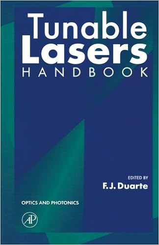
This publication provides an unified and built-in standpoint on tunable lasers and offers researchers and engineers the sensible info they should select a suitable tunable laser for his or her specific purposes. --OPTIK
- Photodetectors and Fiber Optics
- Plasma Sources for Thin Film Deposition and Etching
- Optical Properties of Condensed Matter and Applications (Wiley Series in Materials for Electronic & Optoelectronic Applications)
- Progress in Optics, Vol. 31
Additional info for Applied optics and optical engineering,Vol.III
Sample text
An imperfection or distortion in an image is called an aberration. An aberration can be produced by a flaw in a lens or mirror, but even with a perfect optical surface some degree of aberration is unavoidable. To see why, consider the mathematical approximation we’ve been making, which is that the depth of the mirror’s curve is small compared to do and di. Since only a flat mirror can satisfy this shallow-mirror condition perfectly, any curved mirror will deviate somewhat from the mathematical behavior we derived by assuming that condition.
Dividing by infinity gives zero, so we have 1/do = –1/di , or do = –di . If we interpret the minus sign as indicating a virtual image on the far side of the mirror from the object, this makes sense. It turns out that for any of the six possible combinations of real or virtual images formed by inbending or out-bending lenses or mirrors, we can apply equations of the form θf = θi+θo and 1 f = 1 + 1 di do , with only a modification of plus or minus signs. There are two possible approaches here. The approach we have been using so far is the more popular approach in textbooks: leave the equation the same, but attach interpretations to the resulting negative or positive values of the variables.
Even though the spherical mirror (solid line) is not well adapted for viewing an object at infinity, we can improve its performance greatly by stopping it down. Now the only part of the mirror being used is the central portion, where its shape is virtually indistinguishable from a parabola (dashed line). 44 Chapter 3 Images by Reflection, Part II Summary Selected Vocabulary focal length........................ a property of a lens or mirror, equal to the distance from the lens or mirror to the image it forms of an object that is infinitely far away Notation f .........................................


